In this article, we are going to see what is OSI model and the 7 layers of OSI Model, in computer science and engineering OSI model is the basic model to understand that how the data transfer happens in computer to computer.
Definition of OSI Model
The OSI Model, also known as Open System Interconnection Model, describes and helps to understand how data is transferred between computers in a computer network. The simplest form of the OSI Model is two computers connected together with LAN Cable (Network Media), connectors (RJ45), and sharing data with the help NICs.
Why Do We Need OSI Model
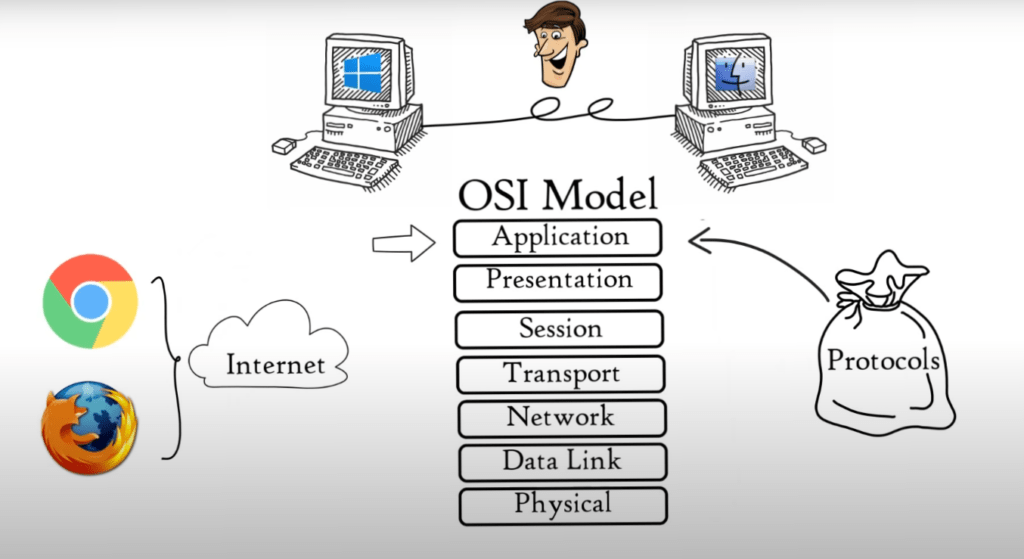
How will two computers communicate with each other if one is running Microsoft Windows and one has macOS? International Organization for Standardization introduced the 7-layered OSI Model, or Open System Interconnection Model, in 1984 to enable successful communication between computers and networks of different architectures:
- Application Layer
- Presentation Layer
- Session Layer
- Transport Layer
- Network Layer
- Data Link Layer
- Physical Layer
Note that each layer is a package of protocols (set of rules and conventions).
(1) Application Layer
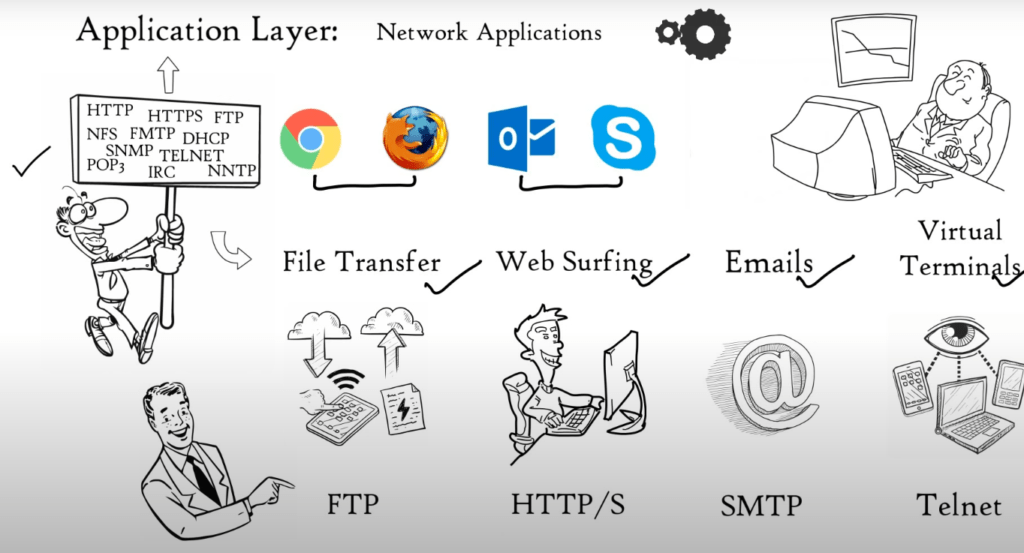
Network applications use the application layer. Network applications are computer programs that access the internet, such as Google Chrome, Firefox and Outlook. A Web Browser is a network program that runs on your computer. It is not located in the Application Layer.
But, It uses application layer protocols (HTTP or HTTPS) to perform web surfing. Web browser is not the only network application, but also Outlook, Skype and other applications. All depend on Application layer protocol to function. Many protocols are available at the Application layer that allow for different functions.
These protocols together form the Application layer. These protocols are the foundation for many network services such as file transfer, email, web surfing, virtual terminals and so on. FTP protocol is used to transfer files. You can surf the web using HTTPS or HTTPS. For email, SMTP protocol and TELNET are used. Application Layer is a layer that provides network services with the aid of protocols to carry out users activities.
(2) Presentation Layer
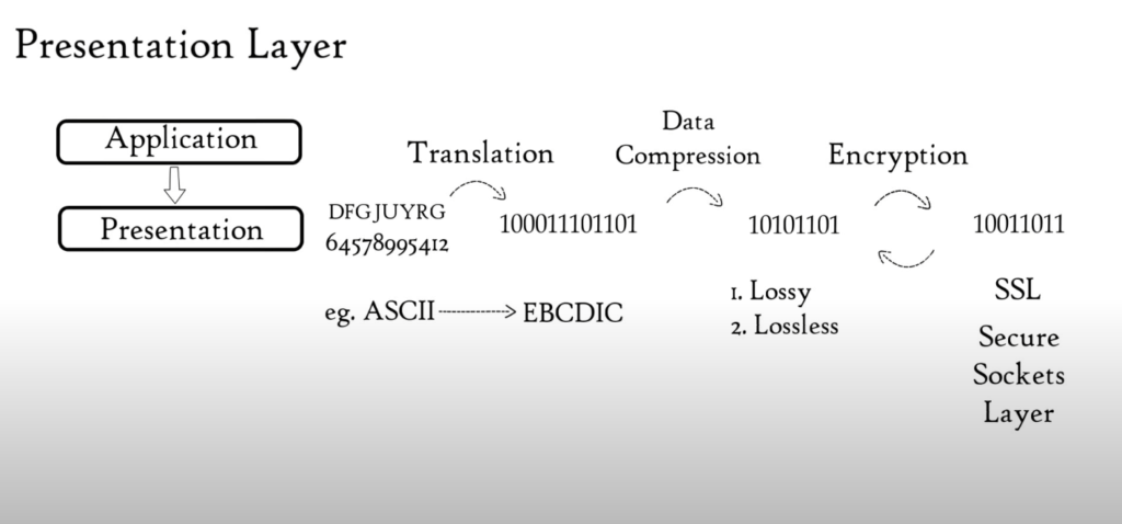
Application Layer sends data to Presentation Layer. These data are in the form of numbers and characters. Presentation Layer convert these characters and numbers to machine-understandable binary format. E.g. Conversion from ASCII code to EBCDIC code This function is known as Translation.
The Presentation Layer reduces bits used to represent original data before data is transmitted. Data compression is a bit reduction process. It can be lossy or lossless. Data compression reduces the space required to store the original file.
The file’s size is smaller, so it takes less time to get to destination. Data transmission can be accomplished faster. Data compression is extremely useful in streaming audio or video real-time. Data encryption is used to protect data integrity before it is transmitted.
Data encryption increases security. Data is encrypted at the sender’s end and decrypted at the receiver’s. For encryption and decryption, Presentation Layer uses SSL protocol (secure sockets layers). The Presentation Layer serves three basic functions: Translation, Compression, Encryption/Decryption.
(3) Session Layer
Let’s say you are planning a party. You hire a few people to help ensure that every activity goes smoothly. You will need help setting up, helping with cleanup, and closing down the party. Session Layer is also available. Session Layer is responsible for setting up and managing connections. It allows sending and receiving data, and then terminating connections.
As you would hire helpers to help you at your party, the Session Layer also has its own helpers known as APIs (application programming interfaces). NetBIOS, or Network Basic Input/output System, is one example of an API that allows different applications to communicate with each others.
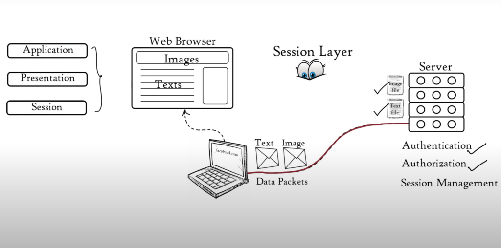
The server performs an authentication function just before a session is established or a connection is made with a server. Authentication is the process by which you verify who you are. The server uses a username or password to do this.
Once your username and password match, you can establish a session (or connection) between your computer’s computer and the server. You can now upload or download the files you need. After authentication, authorization is performed.
The server uses authorization to verify that you have the permission to view a file. If you don’t have permission to access a file, the server will display a message saying “You are not authorized” These functions, Authorization and Authentication, are performed by the session layer.
The session layer keeps track of files downloaded. For example, a web page contains text, images etc. These images and text are saved on the web server as separate files. Your web browser opens a separate session with the web server when you request a website.
This allows you to download all of these images and text files. These files are sent as data packets. Session layer tracks which data packet is associated with which file. This can be either text or image files. It also tracks where the data packets go.
In this case, it goes directly to the web browser. Session Layer helps in Session Management. The session layer assists in: Session Management, Authorization, and Authentication. All functions of session, application and presentation layer are performed by your web browser.
(4) Transport Layer
Through flow control, segmentation and error control, the transport layer ensures reliability in communications. Segmentation is a process where data from the session layer are divided into smaller data units called segments. Each segment includes a source number, Destination number, and sequence number.
Port number is used to direct small data units to the right application. Sequence number is used to assemble smaller data units correctly in order to create a message for the receiver. The Transport Layer regulates the data that is transmitted so that the receiver can process it. Think about our mobile connected to a computer.
Mobile can only process data at 10 Mbps while Server can transmit data at maximum 100 Mbps. We are downloading a file from the server. However, the server begins sending data at 50 Mbps. This is more than the speed that a mobile phone can handle.
The Transport Layer allows the mobile phone to tell the server to slow down data transmission rates up to 10 Mb/s so that data does not get lost. Similarly, if The server is sending data at 5Mbps. The mobile phone informs the server to increase the data transmission speed to 10Mbps to maintain system performance.
Error control is also possible with the help of transport layer. Transport layer can use Automatic repeat request (ARQ), schemes to retransmit corrupted or lost data if some units fail to arrive at the destination. To determine if a data unit has been received incorrectly, checksum is a collection of bits 1s & 0s that are added to each data segment by transport layers.
The Protocols for Transport Layer are Transmission Control Protocol (TCP), and User Datagram Protocol [UDP]. Transport Layer offers two types of services: Connection-oriented Transmission, and Connectionless Transmission.
TCP is used for Connection-Oriented Transmission, while UDP is used for Connectionless Transmission. Let’s say you want to go from Place A to place B. After traveling for some distance, you become stuck in traffic. You have two choices: Follow the same route, or change it according to traffic.
Connection-oriented or TCP Transmission works like option 1, while Connectionless/UDP Transmission works like option 2. Before data transmission, TCP determines the path. The entire connection uses the same route for data packets. TCP conversations are established when a session occurs.
The session ends when the conversation is over. UDP, on the other hand, delivers data packets to users without requiring them to set a path. No session is established. Traffic on available routes will determine the data delivery path.
UDP is quicker than TCP, as it uses a lower traffic route for data delivery. UDP does not provide feedback on whether the data was delivered, while TCP does. TCP can retransmit lost packets. UDP can be used wherever, it doesn’t matter if we have all the data. E.g. You can stream movies, songs, online videos, Voice over IP and TFTP, as well as voice over IP and DNS.
TCP can be used when full data delivery is required. E.g. E.g., World Wide Web, Email and FTP Transport layer is responsible for segmentation, flow control and error control as well as connection and connectionless transmission.
(5) Network Layer
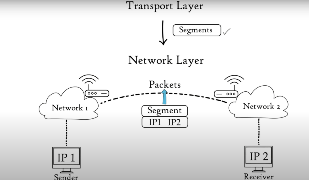
The Transport Layer passes data segments to the Network Layer: The Network layer is responsible for transmitting received data segments between computers located in different networks. The Network Layer segments are known as packets. It is the layer in which routers are located.
The Network layer performs the following functions: Logical Addressing, 2. Routing, 3. Path determination Logical address: This is IP addressing (IPv4 and IPv6) that is done at the network layer. Each computer within a network has a unique IP address. This layer is responsible for data delivery and assigns the sender’s and receiver’s IP addresses to each packet to ensure that it reaches its destination.
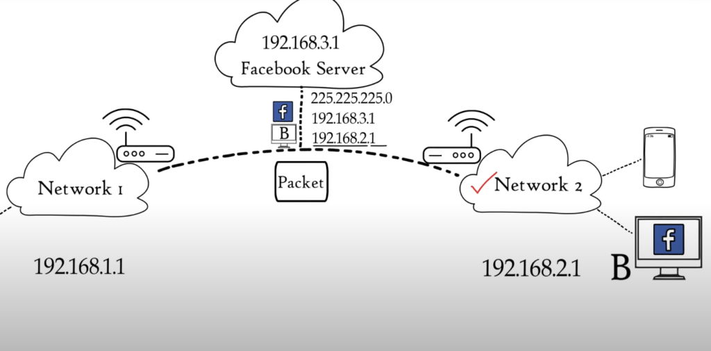
Routing refers to the movement of data packets from source to destination. It is based on IPv4 and IPv6 logical addresses. Let’s say Computer A is connected with network 1, and Computer B is connected with network 2. This simply means that Computer A has multiple smartphones or laptops connected to a Home Router. We have asked to access Facebook.com from computer B.
Now, we receive a packet reply from Facebook server. This packet must be sent to Computer B only. Each device in a network has a unique IP address. This means that both computers will have a unique address. The packet has already been added to the network layer by Facebook server.
The mask indicates that the first three combinations represent network and the last represents host or Computer A. Based on the IP address format, the received data packet will be moved to network B1 then to computer B. Route decisions in a computer network are made based on IP address, mask and other information.
Path determination A computer can connect to any computer or internet server in many ways. Path Determination is the process of determining the best path to data delivery from source and destination. Layer 3 devices use protocols like OSPF (Open Shortest Path First), BGP (Border Gateway Protocol), IS–IS (Intermediate System To Intermediate System) and BGP (Border Gateway Protocol) to determine the best path to data delivery.
(6) Data Link Layer
Data Link Layer receives data packets from Network Layer that contain the IP addresses of the sender and recipient. There are two types of addressing: Logical addressing and Physical addressing. Logical Addressing is done at the network layer, where each data packet is assigned an IP address for both sender or receiver. Physical addressing takes place at Data Link layer, where both the sender and receiver’s MAC addresses are assigned to each data packet.
The manufacturer embeds MAC addresses in the NIC of your computer. Frame is the Data link layer’s data unit. Data Link Layer is embedded in the NIC of a computer. It allows data to be transferred from one computer to another using local media.
Local media include copper wire, optical fiber and Air for radio signals. Media does not include audio, video, animation, etc. It is the physical link between two or more computers, networks. Two basic functions of the Data Link layer are: – It allows upper layers to access media using techniques like framing. – Manages the data received and placed from the media using techniques like media access control and error detection.
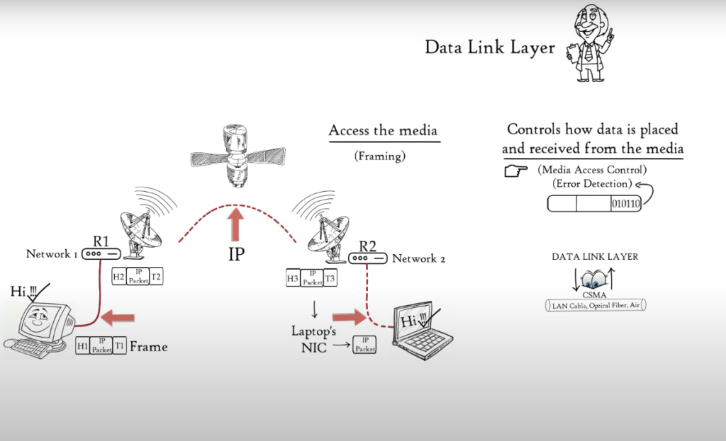
You can access the media by imagining two distant hosts: A laptop and a computer. They will communicate with each other. Because laptop and desktop are connected via different networks, they will use Network Layer Protocols (IP) to communicate with one another. This example shows how the desktop is connected via an Ethernet cable to Router R1.
Router R1 is connected to R2 via a satellite link, and router R2 is connected to the laptop via a wireless link. Now, the desktop needs to send data to the Laptop. Based on the medium that was used to connect desktop to Router R1, Data Link Layer – embedded in NIC of a laptop adds data to head and tail of IP packets and converts them to frames, which is an Ethernet frame.
Router R1 will receive the Ethernet frame and de-capsulate it into an IP packet. Then, it will encapsulate it again to a frame to allow it to cross satellite link to reach router 2. Router R2 will de-capsulate the frame received and re-encapsulate it based on the medium used for connecting router R2 to laptop. In this instance, the wireless data link frame. Laptop receives wireless link frame and will de-capsulate it before forwarding IP packet to Network layer, and finally to the application layer.
The application layer protocols allow the received data to be displayed on the computer screen. Data Link Layer allows network layer and higher-level layers to transfer data via media (LAN Cable or Air). Data Link Layer allows access to media for OSI Model’s higher layers.
Data Link Layer controls how data is received and placed from the media. Data Link Layer receives and sends frames from the media. Media Access Control is the technique that allows the frame to be transferred onto and off the media. Multiple devices may be connected to the same media.
Two or more devices may send data simultaneously, which could lead to collisions that result in messages that are not understood by the recipients. Data link layer monitors when shared media is available so that the receiver can receive data.
This is Carrier Sense Multiple Access CSMA. Data Link Layer with its Media Access Control methods controls when data is received and placed from the media. Each frame’s tail contains bits that are used to detect errors in the receiving frame. These errors are caused by limitations in media that can be used to transfer data.
(7) Physical Layer
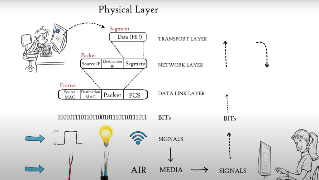
Data from the application layer was segmented by Transport Layer, put into packets by Network Layer, and then framed by Data Link Layer. This is a sequence of binary 0s or 1s. This binary sequence is converted into signals by the Physical Layer and transmitted over local media. It could be an electrical signal for Copper Cable, LAN cable or Optical Fiber, or a light signal for Optical Fiber. Radio signals are used in local media such as Air.
The type of Media used for connecting two devices will determine the signal that the Physical Layer generates. The physical layer at the receiver receives signals and converts them into bits. The frame is then passed to the Data Link Layer, which in turn passes it on to higher layers and finally to the application layer. The application layer protocols make the sender’s message available in the application on the receiver’s computer screen. These are the 7 OSI Model layers that are responsible for Internet’s smooth operation.
